- 您现在的位置:买卖IC网 > Sheet目录1252 > VR1005CCA270-T (Taiyo Yuden)VARISTOR 27V 15PF 0402 SMD
�� �
�
�■� PRECAUTIONS�
�Precautions� on� the� use� of� Multilayer� chip� varistors.�
�3.� Considerations� for� automatic� placement�
�◆� Adjustment� of� mounting� machine�
�1.� Excessive� impact� load� should� not� be� imposed� on� the� varistors� when� mounting� onto� the� PC� boards.�
�Precautions�
�2.� The� maintenance� and� inspection� of� the� mounters� should� be� conducted� periodically.�
�◆� Selection� of� Adhesives�
�1.� Mounting� varistors� with� adhesives� in� preliminary� assembly,� before� the� soldering� stage,� may� lead� to� degraded� varistor� characteristics� unless� the� following�
�factors� are� appropriately� checked;� the� size� of� land� patterns,� type� of� adhesive,� amount� applied,� hardening� temperature� and� hardening� period.� Therefore,� it� is�
�imperative� to� consult� the� manufacturer� of� the� adhesives� on� proper� usage� and� amounts� of� adhesive� to� use.�
�◆� Adjustment� of� mounting� machine�
�1.� If� the� lower� limit� of� the� pick-up� nozzle� is� low,� too� much� force� may� be� imposed� on� the� capacitors,� causing� damage.� To� avoid� this,� the� following� points� should�
�be� considered� before� lowering� the� pick-up� nozzle� :�
�(� 1� )� The� lower� limit� of� the� pick-up� nozzle� should� be� adjusted� to� the� surface� level� of� the� PC� board� after� correcting� for� de?ection� of� the� board.�
�(� 2� )� The� pick-up� pressure� should� be� adjusted� between� 1� and� 3N� static� loads.�
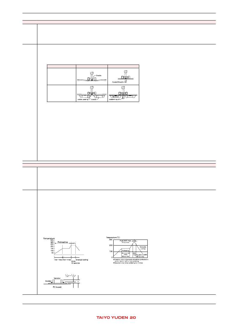
�(� 3� )� To� reduce� the� amount� of� de?ection� of� the� board� caused� by� impact� of� the� pick-up� nozzle,� supporting� pins� or� back-up� pins� should� be� used� under� the� PC�
�board.� The� following� diagrams� show� some� typical� examples� of� good� pick-up� nozzle� placement� :�
�Technical�
�consider-�
�Single-sided� mounting�
�Double-sided� mounting�
�Not� recommended�
�Recommended�
�ations�
�2.� As� the� alignment� pin� wears� out,� adjustment� of� the� nozzle� height� can� cause� chipping� or� cracking� of� the� varistors� because� of� mechanical� impact� on� the�
�varistors.� To� avoid� this,� the� monitoring� of� the� width� between� the� alignment� pin� in� the� stopped� position,� and� maintenance,� inspection� and� replacement� of� the�
�pin� should� be� conducted� periodically.�
�◆� Selection� of� Adhesives�
�1.� Some� adhesives� may� cause� reduced� insulation� resistance.� The� difference� between� the� shrinkage� percentage� of� the� adhesive� and� that� of� the� varistors� may�
�result� in� stresses� on� the� varistors� and� lead� to� cracking.� Moreover,� too� little� or� too� much� adhesive� applied� to� the� board� may� adversely� affect� component�
�placement,� so� the� following� precautions� should� be� noted� in� the� application� of� adhesives.�
�(� 1� )� Required� adhesive� characteristics�
�a.The� adhesive� should� be� strong� enough� to� hold� parts� on� the� board� during� the� mounting� &� solder� process.�
�b.The� adhesive� should� have� suf� ?cient� strength� at� high� temperatures.�
�c.The� adhesive� should� have� good� coating� and� thickness� consistency.�
�d.The� adhesive� should� be� used� during� its� prescribed� shelf� life.�
�e.The� adhesive� should� harden� rapidly.�
�f.� The� adhesive� must� not� be� contaminated.�
�g.The� adhesive� should� have� excellent� insulation� characteristics.�
�h.The� adhesive� should� not� be� toxic� and� have� no� emission� of� toxic� gasses.�
�(� 2� )� When� the� amount� of� adhesive� is� inappropriate� to� mount� varistors� on� a� PCB,� that� may� cause� a� problem� in� placement� of� the� component.�
�Too� little� adhesive� may� cause� the� varistors� to� fall� off� the� board� during� the� solder� process.�
�Too� much� adhesive� may� cause� defective� soldering� due� to� excessive� ?ow� of� adhesive� on� to� the� land� or� solder� pad.�
�4. Soldering�
�◆� Selection� of� Flux�
�1.� Since� ?ux� may� have� a� signi?cant� effect� on� the� performance� of� varistors,� it� is� necessary� to� verify� the� following� conditions� prior� to� use� ;�
�(� 1� )� Flux� used� should� be� with� less� than� or� equal� to� 0.1� wt%� (equivalent� to� chlorine)� of� halogenated� content.� Flux� having� a� strong� acidity� content� should� not� be�
�Precautions�
�applied.�
�(� 2� )� When� soldering� varistors� on� the� board,� the� amount� of� ?ux� applied� should� be� controlled� at� the� optimum� level.�
�(� 3� )� When� using� water-soluble� ?ux,� special� care� should� be� taken� to� properly� clean� the� boards.�
�◆� Soldering�
�1.� Temperature,� time,� amount� of� solder,� etc.� are� speci?ed� in� accordance� with� the� following� recommended� conditions.�
�◆� Selection� of� Flux�
�1-1.� When� too� much� halogenated� substance� (Chlorine,� etc.)� content� is� used� to� activate� the� ?ux,� or� highly� acidic� ?ux� is� used,� an� excessive� amount� of� residue� after�
�soldering� may� lead� to� corrosion� of� the� terminal� electrodes� or� degradation� of� insulation� resistance� on� the� surface� of� the� varistors.�
�1-2.� Since� the� residue� of� water-soluble� ?ux� is� easily� dissolved� by� water� content� in� the� air,� the� residue� on� the� surface� of� varistors� in� high� humidity� conditions� may�
�cause� a� degradation� of� insulation� resistance� and� therefore� affect� the� reliability� of� the� components.� The� cleaning� methods� and� the� capability� of� the� machines�
�used� should� also� be� considered� carefully� when� selecting� water-soluble� ?ux.�
�◆� Soldering�
�1-1.� Preheating� when� soldering�
�Heating� :� Ceramic� chip� components� should� be� preheated� to� within� 100� to� 130� ℃� of� the� soldering.�
�Cooling� :� The� temperature� difference� between� the� components� and� cleaning� process� should� not� be� greater� than� 100� ℃� .�
�Ceramic� chip� varistors� are� susceptible� to� thermal� shock� when� exposed� to� rapid� or� concentrated� heating� or� rapid� cooling.� Therefore,� the� soldering� process�
�must� be� conducted� with� great� care� so� as� to� prevent� malfunction� of� the� components� due� to� excessive� thermal� shock.�
�Recommended� conditions� for� soldering�
�[Re?ow� soldering]�
�Temperature� pro?le�
�Technical�
�consider-�
�ations�
�Caution�
�1.� The� ideal� condition� is� to� have� solder� mass� (?llet)� controlled� to� 1/2� to� 1/3� of� the� thickness� of� the� varistor,� as� shown� below� :�
�2.� Because� excessive� dwell� times� can� detrimentally� affect� solder� ability,� soldering� duration� should� be� kept� as� close� to� recommended� times� as� possible.�
�*� This� catalog� contains� the� typical� speci� ?cation� only� due� to� the� limitation� of� space.� When� you� consider� the� purchase� of� our� products,� please� check� our� speci� ?cation.�
�For� details� of� each� product� (characteristics� graph,� reliability� information,� precautions� for� use,� and� so� on),� see� our� Web� site� (http://www.ty-top.com/)� or� CD� catalogs.�
�chipv0102_reli_e-01�
�12�
�chipv0102_reli-PRP5�
�发布紧急采购,3分钟左右您将得到回复。
相关PDF资料
VR15AT18A650R
VARISTOR 18VDC 30A 150C RAD
VS230A
GAS TUBE GDT 230V AXIAL TR
VSHLD-EMR
VINCO ETHERNET MP3 RTC SHIELD
VSUPEV2
BOARD EVAL FOR MCP4022,4023,4024
VSUPEV
BOARD EVAL VOLT SUPERVISOR SOT23
VTERB-BLK-X2-UT4
LICENSE VITERBI DECODER XP2
VTERB-DECO-XP-N1
IP CORE VITERBI DECODER XPGA
VTP110F
POLYSWITCH PTC RESET 1.1A STRAP
相关代理商/技术参数
VR1005DDA080-T
制造商:TAIYO YUDEN 功能描述:Cut Tape 制造商:Taiyo Yuden 功能描述:0
VR100B080CU-2C
功能描述:DC/DC转换器 VRM10VID 1U 80A 12V to 0.8375-1.60V RoHS:否 制造商:Murata 产品: 输出功率: 输入电压范围:3.6 V to 5.5 V 输入电压(标称): 输出端数量:1 输出电压(通道 1):3.3 V 输出电流(通道 1):600 mA 输出电压(通道 2): 输出电流(通道 2): 安装风格:SMD/SMT 封装 / 箱体尺寸:
VR101
制造商:Fluke Electronics 功能描述:RECORDER VOLTAGE EVENT
VR101/001
制造商:Fluke Electronics 功能描述:RECORDER GERMAN VER FLUKE VR101/001
VR101/003
功能描述:数据记录与采集 VOLTAGE EVENT RECO
RoHS:否 制造商:Lantronix 描述/功能:Analog device server 显示器类型:None 电流额定值:
VR101/004
制造商:Fluke Electronics 功能描述:Additional VR101 voltage event recorder
VR101S
制造商:Fluke Electronics 功能描述:RECORDER VOLTAGE EVENT
VR101S/003
功能描述:数据记录与采集 VOLTAGE EVENT RECO
RoHS:否 制造商:Lantronix 描述/功能:Analog device server 显示器类型:None 电流额定值: